| HOME |
| Introduction |
| The Layout Plan |
| Fictional history |
| Construction Projects |
| Stock |
| Contact Me |
Baseboards
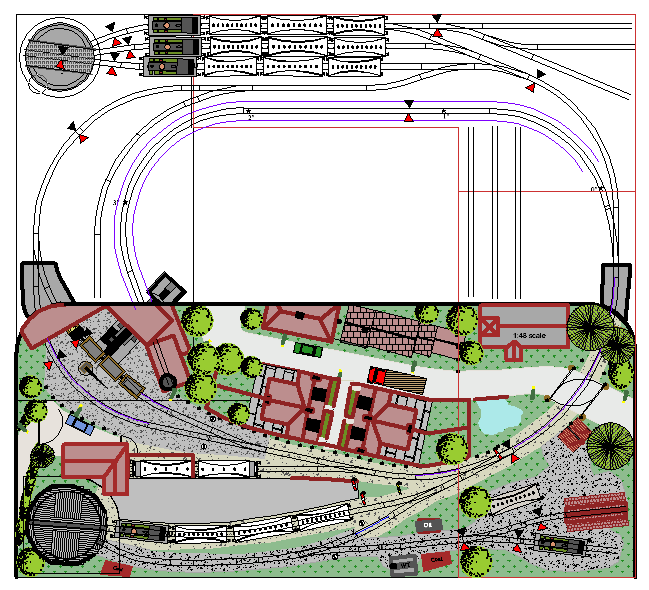
Bearing in mind the design requirements, and addressing firstly the size and shape it consists of five separate baseboards. Each has a maximum width of 22 inches and two are 55 inches long and two are 48 inches long. This gives an overall size of 77 inches x 70 inches - a good fit into the available space - and each baseboard is small enough to go through the loft hatch and to fit in the car.
The fifth baseboard is the odd one out. Although it fits within the same
maximum size constraints, it actually overlaps the front baseboard(s)
and reaches back into the central well. This gives a maximum depth to
the scenic part of the layout of 34 inches, compensating in part for the
lack of length/width.
In addition that boards front and side edges follow natural scenic
breaks as much as possible - quarry buildings to the left, house and
garden walls to the front, and walls and shop ends to the right. This,
hopefully, will reduce the effect of the join between baseboards which
will no longer be a straight front to back mini-crevasse!

Background description
The model is intended to represent Sompting Lambley station. Part of the village is modelled behind the station. To the left, the line runs into an off-scene quarry which is no longer active as such. It now contains the railway's coach and engineering sheds. In addition, materials for the construction of the new line are stored here and old spoil from the quarry is currently being loaded onto wagons at the quarry entrance and taken away to repair the causeway over the River Sump's water meadows for the extension.
Originally, the passenger station was minimal and, in fact included
rather dilapidated engine and carriage sheds. They, however, were resited
and the station re-built primarily as a passenger terminus although
still using the turntable that formerly served the engine shed, but now
to enable locos to run around their trains.
A more detailed history of the line itself can be found by following the "Fictional History" link.
Operation
Passenger trains enter from the right, passing through dense woodland next to the small church, over the level crossing and then entering the main platform. Locos can uncouple, turn and run-around, use the servicing facilities to the right and then return to their train. Alternatively another loco already in the servicing area could take over or even a "fresh" one from the quarry line.
The train can then return, past the church again and disappear towards the hidden sidings which represent Broadsteyne. These also, to allow hands-off operation, have a turntable to allow run-around etc. There are three small storage roads for spare coaches and locos. Occasional short trains, generally railcars, will also emerge from the hidden sidings but will usually pull into the small bay platform from which they reverse out and then continue past the bay into the quarry carrying both volunteers and for tours of the storage and works sheds.
In the meantime, trains of empty open trucks can again emerge past the church and pull into the loop at the quarry entrance for loading. Again, their loco can uncouple and run-around while they are loaded via conveyer belt. Once loaded they are taken back out towards the new junction leading the the new extension - in reality to a rising gradient around the back of the layout which takes them to the top of the conveyor for off-scene unloading.
Other "goods" trains can also emerge from the quarry to the left carrying other materials such as rails for the extension, or coal or oil for the stations basic loco servicing facilities. Similarly, additional coaches and locos can be brought in from the carriage and works sheds in the quarry. This latter can be achieved because the track between the entry to the hidden sidings and the backscene is long enough to hold a complete train.
Last, but not least, the continuous run can be used for testing, running in or just entertaining people while trying to deal with some more complex operational issue!
Electrics
As previously noted the layout is wired for DCC. Simplistically, in this case, this means that there are just 8 wires passing between baseboards. These 8 wires are fairly heavy duty (trailer cable) since they may carry quite high currents and are arranged as four pairs. They are:-
- Black and red - twisted pair carrying the track DCC bus
- Blue and brown - twisted pair carrying the accessories DCC bus
- Green and yellow - accessories power (16v AC)
- White and green/yellow - auxiliary power (lights etc - 12v AC)
You will note that there are two DCC buses. This allows the trains themselves to be controlled independently (via an NCE Power Cab) from the points etc which are controlled from a mimic panel using DPDT switches to drive MERG Accessory Encoders/decoders - the secondary pole driving LEDS on the mimic panel reflecting the set route.
NEXT: The railway's (fictional) history